Six-Pack Basics: Your Guide to Primary Flight Instruments

You’ll never forget your first cockpit. Surrounded by switches, dials, and blinking lights — it’s overwhelming at first. But front and centre sits a classic layout that every pilot, from student to seasoned airline captain, learns to trust: the six-pack.
Even in today’s digital glass cockpits, these six primary flight instruments form the backbone of your situational awareness. Whether you’re flying a humble Cessna 152 or transitioning into a jet, understanding the six-pack means figuring out your aircraft — and staying ahead of it.
This guide will walk you through the six essential flight instruments every pilot must know. We’ll break them down into gyroscopic and pitot-static categories, explain how they work, and show you how to interpret what they’re telling you.
Let’s take it from the top—instrument by instrument.
What Is the Six-Pack in Aviation?
Before digital glass cockpits and multifunction displays, pilots relied on a simple, reliable layout of six core instruments—informally known as the “six-pack.” These analogue gauges are the backbone of any VFR or IFR flight and are still found in most general aviation aircraft today.
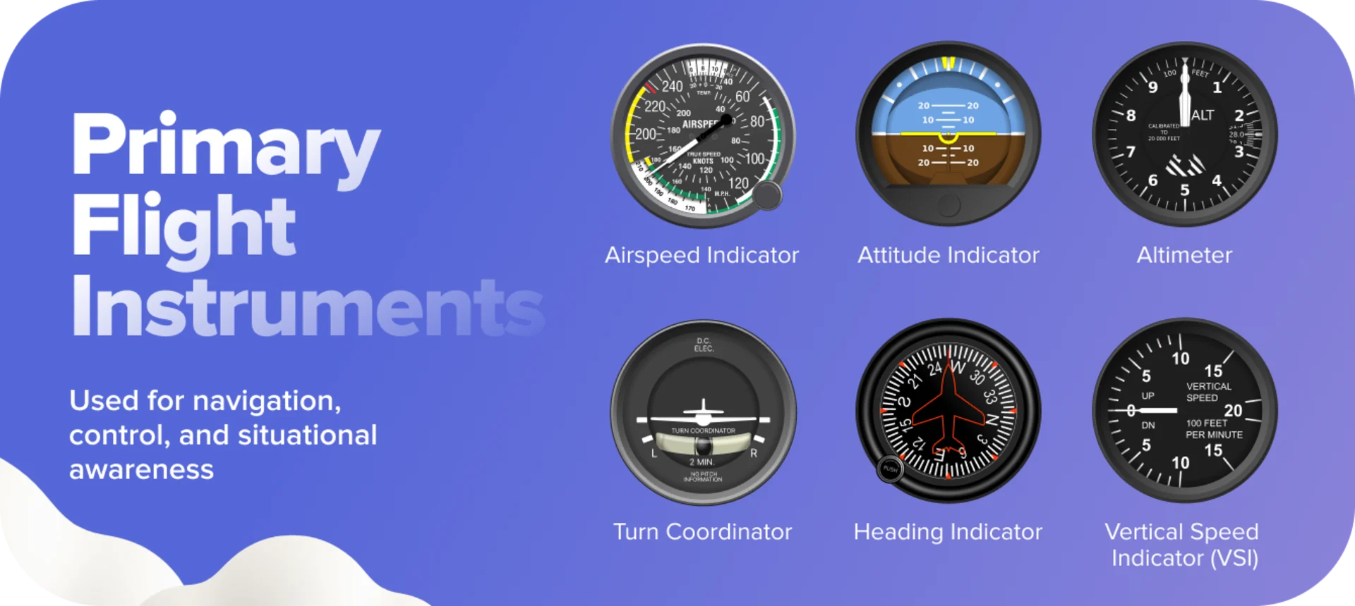
The six-pack gives pilots essential real-time data about the aircraft’s speed, attitude, altitude, and movement in space. Arranged in a standard two-row, three-column grid, they provide a quick scan pattern to help pilots keep their eyes outside the cockpit while still maintaining full situational awareness.
Here’s the typical layout:
Top row (left to right):
Airspeed Indicator
Attitude Indicator
Altimeter
Bottom row (left to right):
Turn Coordinator
Heading Indicator (Directional Gyro)
Vertical Speed Indicator (VSI)
Though newer aircraft may use digital displays, learning the six-pack is still a fundamental part of pilot training. These instruments teach you how to interpret core flight data — skills that remain essential even in the age of glass cockpits.
Why is it called the “six-pack”? Just like a pack of soda cans—six neatly grouped units you rely on every flight. Ready to break them down? Let’s start with the gyroscopic instruments.
Nervous about your first ATC call? Don't worry, we've got you covered. Check out our guide to help you navigate your initial radio communications.
Gyroscopic Instruments
Stability in Motion
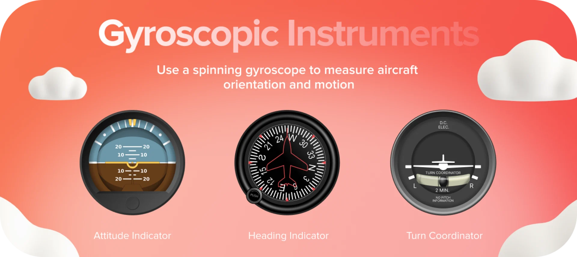
Three of the six primary flight instruments rely on the physics of gyroscopes. These spinning wheels might be small, but they give pilots incredibly precise information about the aircraft’s orientation and movement.
How do gyroscopes work? A gyroscope is a spinning disc mounted on gimbals, which allows it to rotate freely around one or more axes. Its core property is called rigidity in space — a gyroscope tends to stay fixed in its orientation, even as the aircraft moves around it. This provides a stable reference point for measuring angular movement.
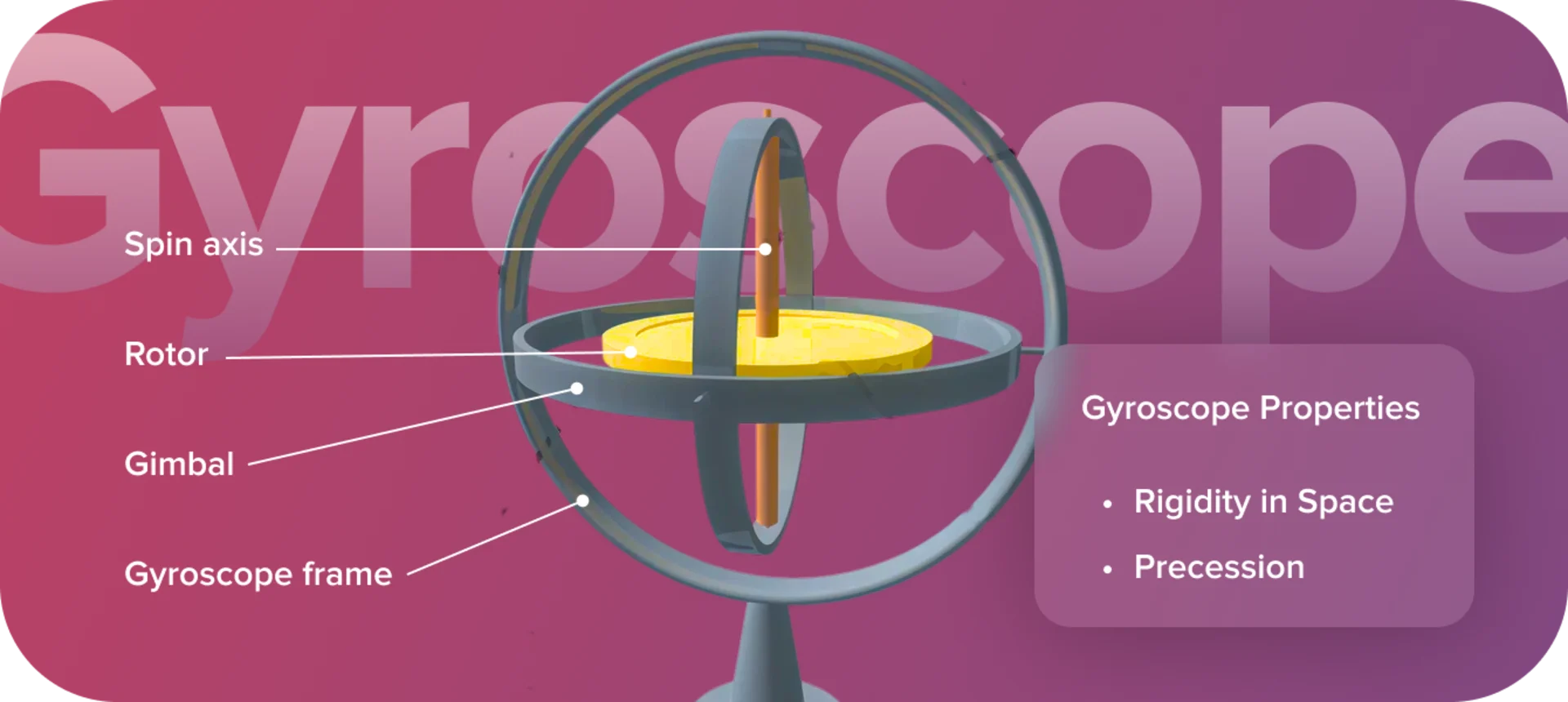
Another important principle is precession, where a force applied to the spinning disc results in a movement 90 degrees later in the direction of rotation. This phenomenon is useful (and sometimes tricky) in aviation instruments, where it can introduce drift that needs occasional correction.
Together, these three gyroscopic instruments give you a real-time picture of your aircraft’s attitude, heading, and turn rate—vital for safe and precise flight, especially when flying under instrument rules or in reduced visibility.
Master the nuances of gyroscope behaviour with our “Gyroscope Wander” blog. You'll learn to spot faults, comprehend real wander, and gain key insights into toppling and drift. Want to revisit the fundamentals? Our video on Gyroscope Properties is ready for you here.
Attitude Indicator (AI)
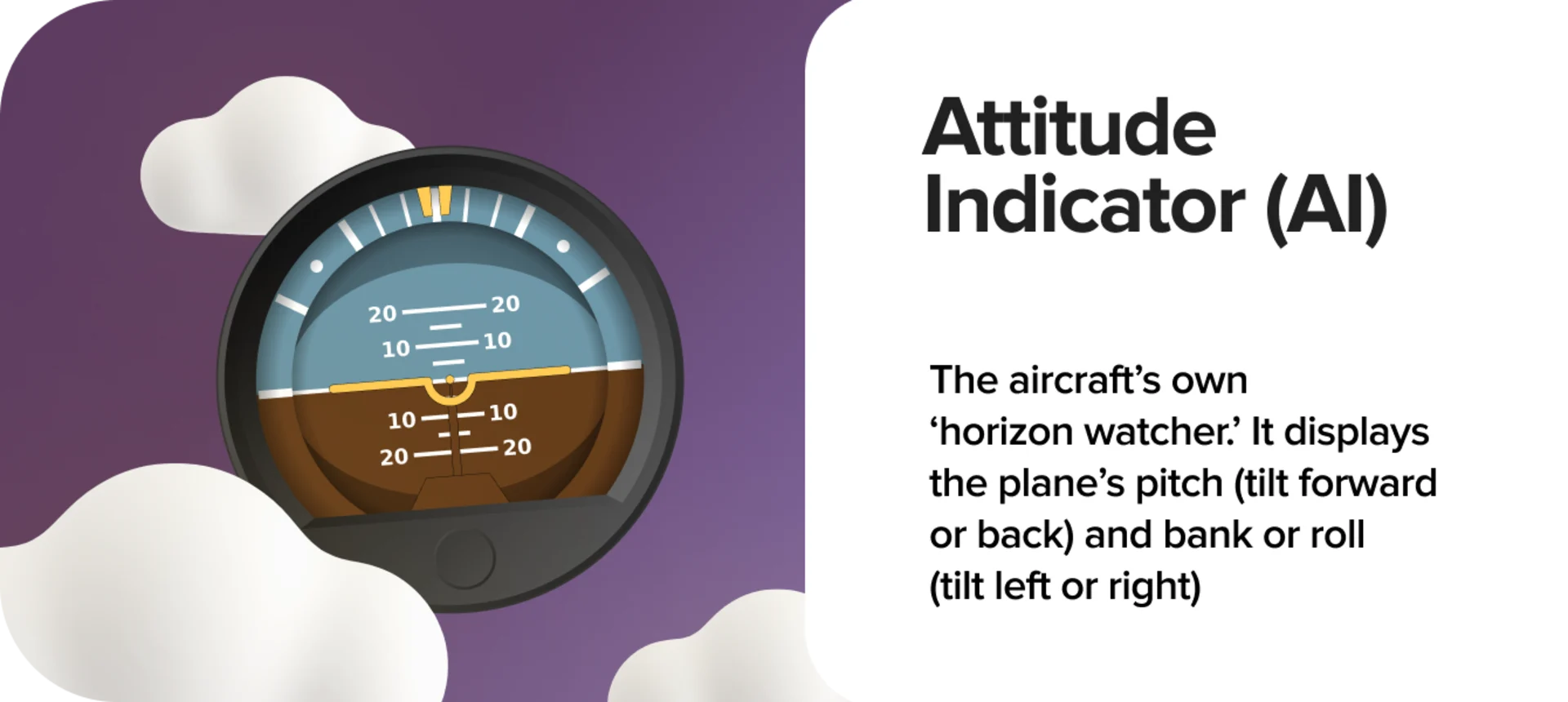
The Attitude Indicator, or Artificial Horizon, is your go-to instrument for spatial orientation. It shows the aircraft’s pitch (nose-up or nose-down) and bank (left or right tilt) relative to the true horizon.
Attitude Indicator forms the foundation of your instrument scan, especially in instrument meteorological conditions (IMC). It tells you whether the aircraft is climbing, descending, or banking. The markings include reference bars for pitch (in degrees) and bank angles, making attitude interpretation precise.
Vacuum-driven AI systems typically work reliably up to ±100° of bank and ±60° of pitch. Exceeding these limits can cause the instrument to “topple” (lose reference). It may take time to reset once the aircraft returns to normal flight.
Are you aware of the attitudes that can sabotage your flying? Discover 5 risky mindsets every pilot should check.
Heading Indicator (HI)
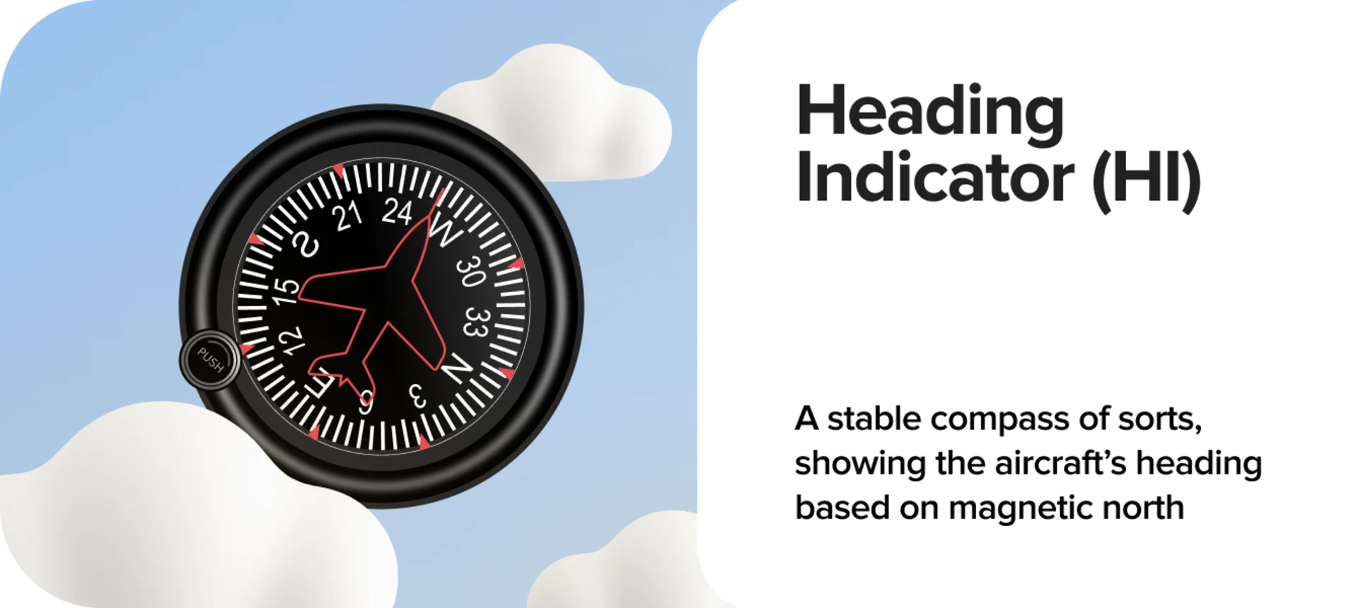
The Heading Indicator (also called Directional Gyro or DG) gives you a stable directional reference — not easily thrown off by turbulence or acceleration like the magnetic compass.
The main purpose of HI is to display your current heading in degrees. Some HIs include a “bug” you can set to mark a desired heading, a handy aid during navigation or ATC vectors. There are limitations with the heading indicator. It drifts over time due to precession and must be realigned with the magnetic compass periodically.
Note: Don’t confuse the HI with the Horizontal Situation Indicator (HSI), which adds VOR and ILS navigation elements to a heading display.
Turn Coordinator (TC)
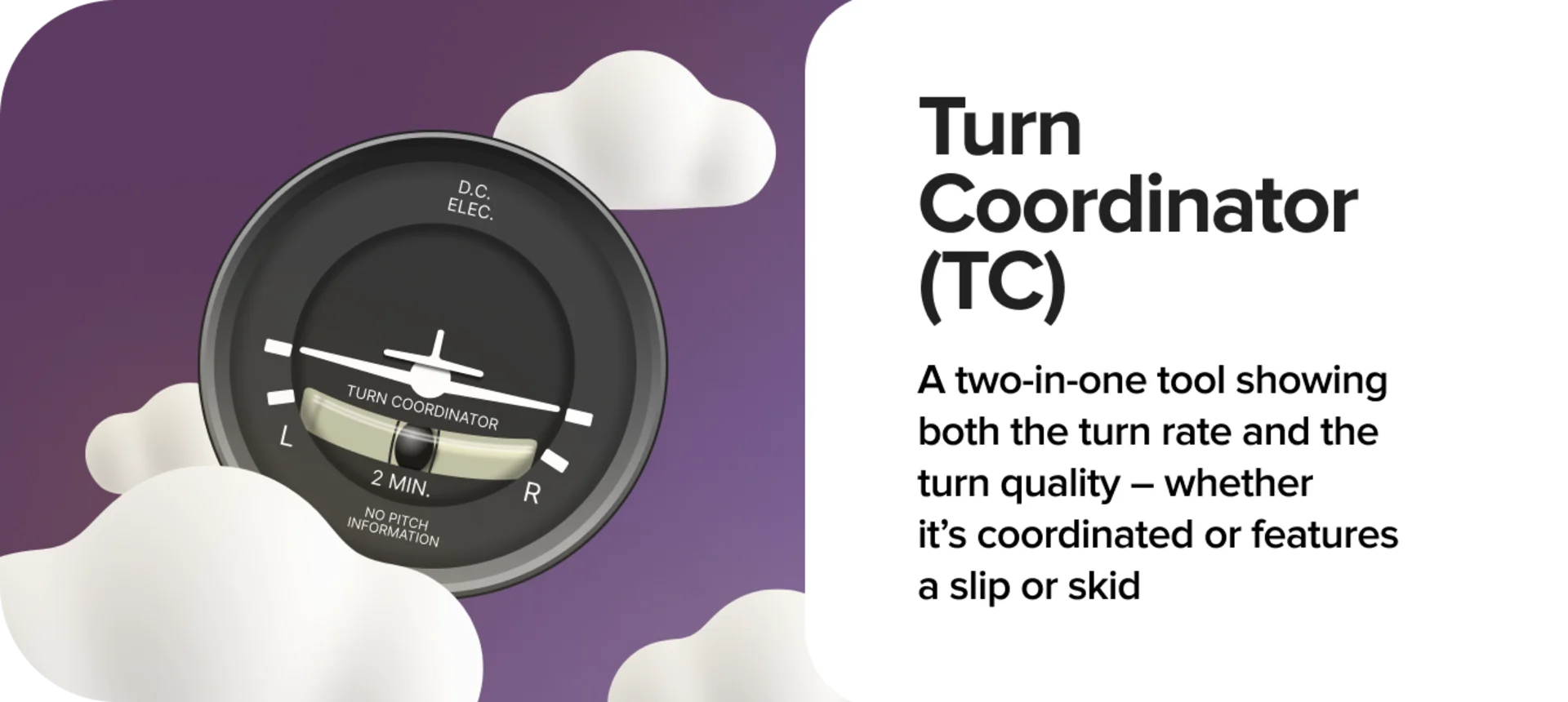
The Turn Coordinator is a dual-function instrument. It shows both rate of turn and coordination, helping you stay in balanced flight.
A miniature aircraft or bar shows your roll and rate of turn. Standard-rate turns (3° per second) are marked for quick reference, these are essential for instrument flight procedures. A liquid-filled curved tube contains the small black inclinometer ball (sometimes called “the ball in the tube”). It tells you whether the aircraft is in coordinated flight, or if you're slipping or skidding through the sky.
When the ball is centred, your horizontal component of lift and your yaw are in harmony — you’re in coordinated turn.

In a slip, the aeroplane is banked, but you're not using enough rudder in the direction of the turn. The aircraft’s tail is “hanging inside” the turn, and you're not turning as tightly as your bank angle suggests. You’ll feel like you're sliding sideways into your seat. The ball in the tube moves into the turn (toward the inside of the curve). To fix it, add more rudder in the direction of the turn.
In a skid, you're overdoing it, applying too much rudder for the bank angle. This can be dangerous, especially in slow flight or near a stall, because it can lead to a spin. You’ll feel like you're getting thrown outward in the turn. The ball moves away from the turn (toward the outside of the curve). Reduce rudder input or increase bank angle to match the rate of yaw.

Smarter flying starts here. Explore 8 Rules of Thumb for more intuitive and efficient flying.
Pitot-Static Instruments
Reading Speed, Altitude, and Vertical Motion
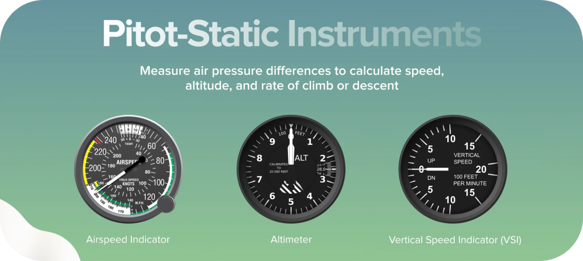
The other half of your trusty six-pack relies on a clever use of air pressure. These instruments are powered by the pitot-static system, which collects air pressure from two sources:
Pitot tube → Measures dynamic pressure (caused by the aircraft moving through air).
Static port → Measures ambient static pressure (air pressure at your current altitude).
By comparing these two, your aircraft determines how fast you’re going, how high you are, and how quickly you're climbing or descending.
Airspeed Indicator (ASI)
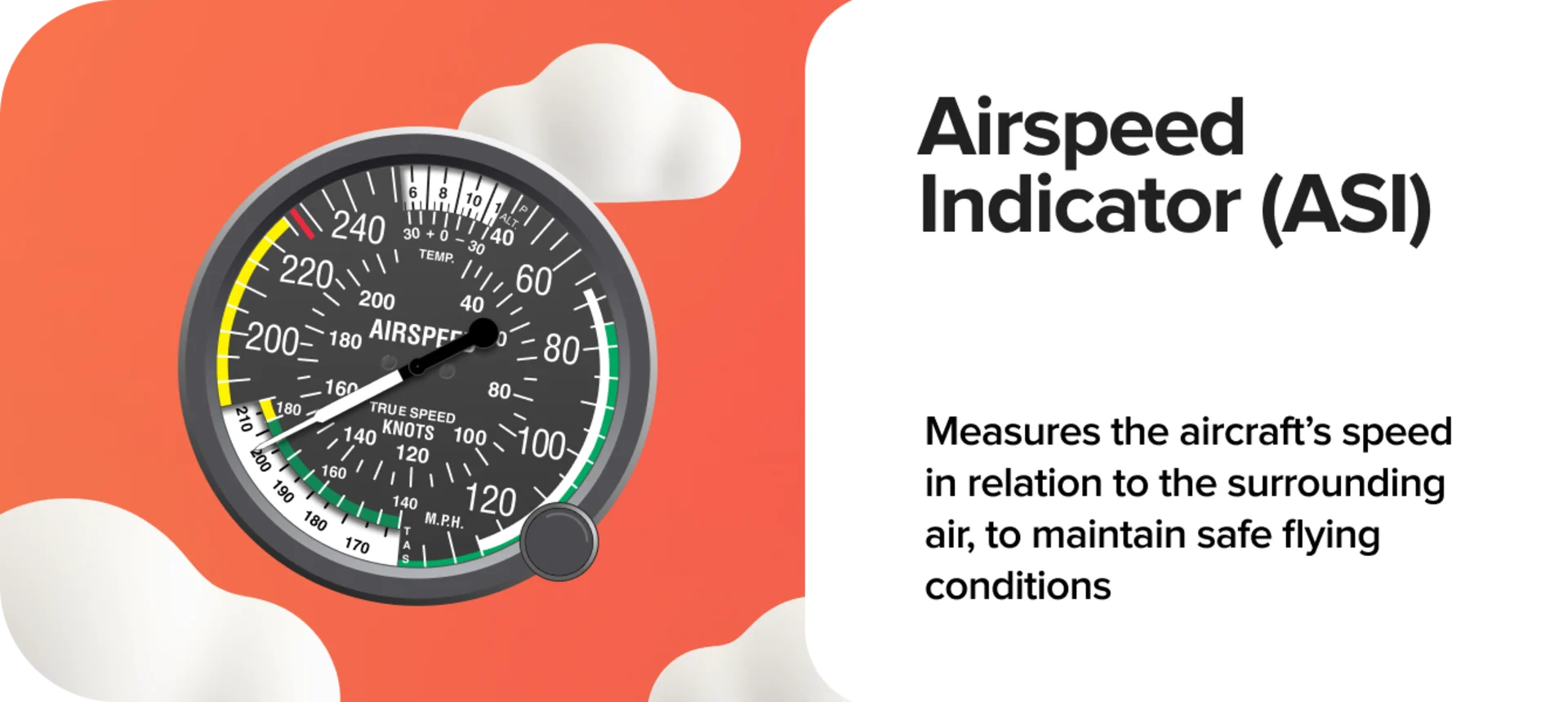
The Airspeed Indicator displays your indicated airspeed (IAS) in knots or MPH; this reading does not account for temperature or altitude effects. You’ll learn about True Airspeed (TAS) and Calibrated Airspeed (CAS) later in your training.
ASI compares the pressure from the pitot tube (which captures ram air as you move forward) to the static pressure. The difference is the dynamic pressure, which is directly related to airspeed.
The indicator consists of coloured rings within the dial:
White Arc: Flap operating range
Green Arc: Normal operating range
Yellow Arc: Caution zone, should only be entered in calm air
Red Radial: Never exceed speed
Fly safely across Europe. Our guide, See and Be Seen: Rules for Safe VFR Flying, breaks down the essential VFR rules you must know for confident piloting.
Altimeter
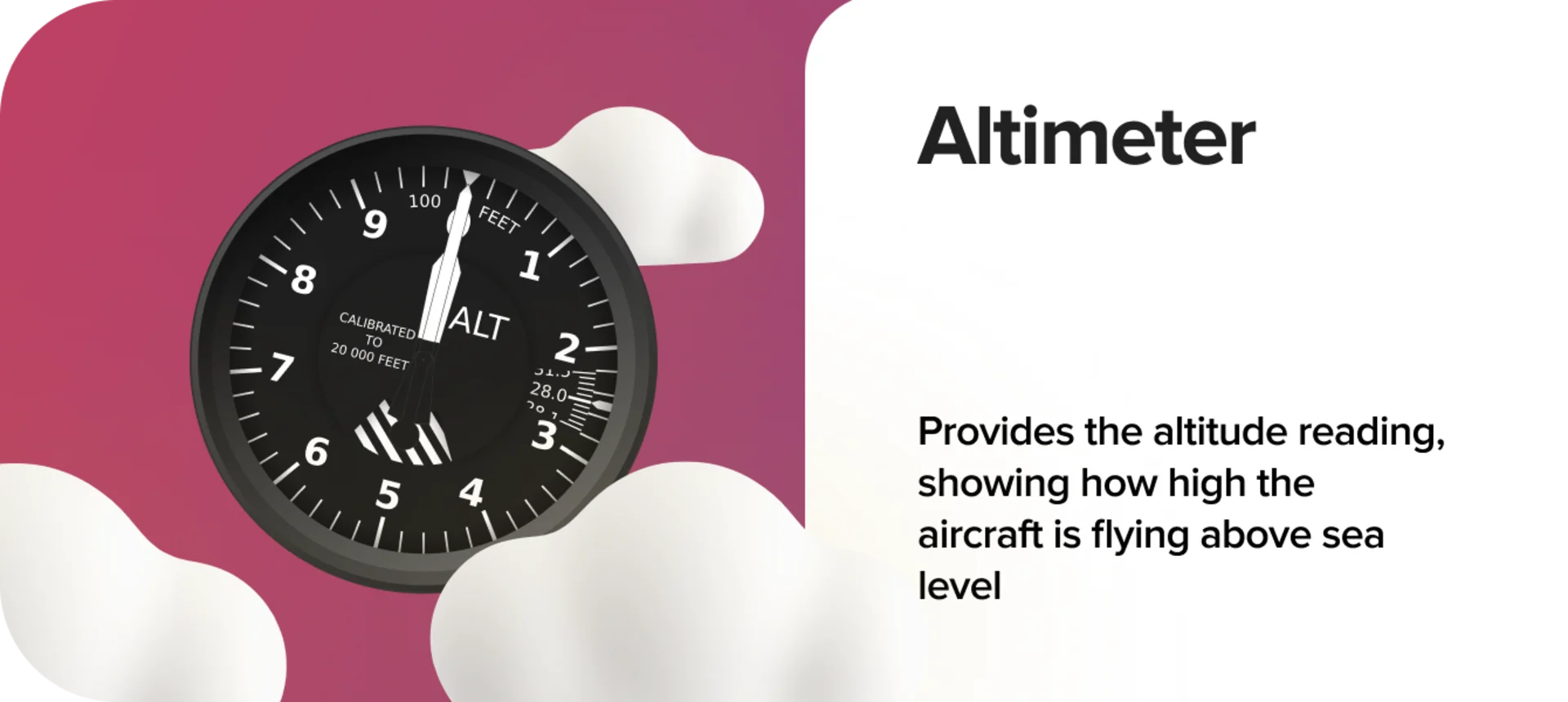
The Altimeter gives you altitude by comparing static pressure with a pre-set reference value. The air pressure around you drops as altitude increases. The altimeter senses this drop via the static port, then converts it into a reading on a calibrated dial. Most altimeters have two or three pointers, showing hundreds, thousands, and tens of thousands of feet.
A mis-set altimeter pressure can result in significant altitude errors. Always reset your pressure setting with updated ATIS or tower info. High to low, look out below!
Do you know the difference between true altitude and pressure altitude? Find out the answer and learn about other types of altitude in our blog: Altitude Basics: 5 Types Of Altitude Explained.
Vertical Speed Indicator (VSI)
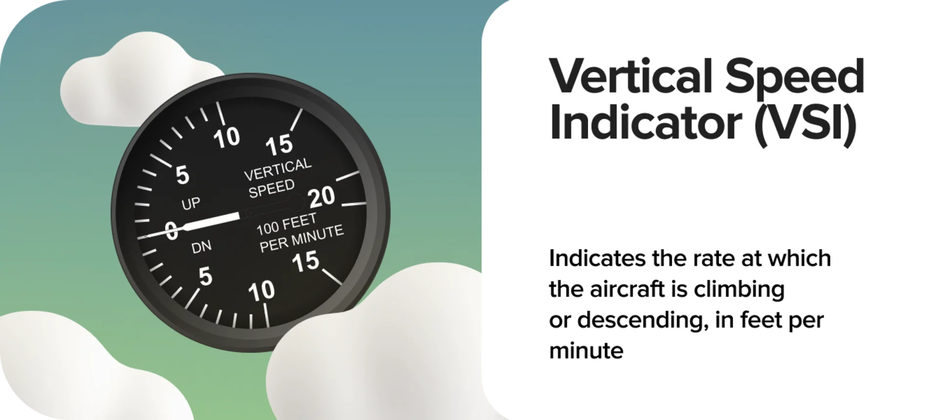
The Vertical Speed Indicator helps you keep your climbs and descents smooth and precise. It senses the rate of change in static pressure via a calibrated leak. If the pressure is decreasing rapidly (as in a climb), it shows a positive climb rate. If it increases (as in a descent), it shows a negative rate.
Readout displays a rate of climb or descent in feet per minute (fpm), typically ±1,000 fpm or ±2,000 fpm. The VSI has a lag of a few seconds, so don’t chase it during quick attitude changes, use your attitude indicator and pitch references instead.
Want to know the science behind your airspeed readings? Review our latest blog: Pitot Tube 101: How Your Airspeed Indicator Works.
Airhead's Takeaway

At first glance, the aircraft’s instrument panel can feel like a wall of dials. Every experienced pilot once stared at that same six-pack with wide eyes and a racing pulse. So if you ever feel overwhelmed, take a breath, trust your training, and focus on progress. Aviation is a discipline of patience and precision, where even the smallest learning moment adds up to real mastery.
And remember: great pilots aren't born—they’re built, dial by dial, turn by turn, scan by scan. Trust the process. You’ve got this.


